

Installation of our automated point motors.
- Bushey Miniature Railway

- Mar 3, 2020
- 4 min read
Updated: Mar 4, 2020

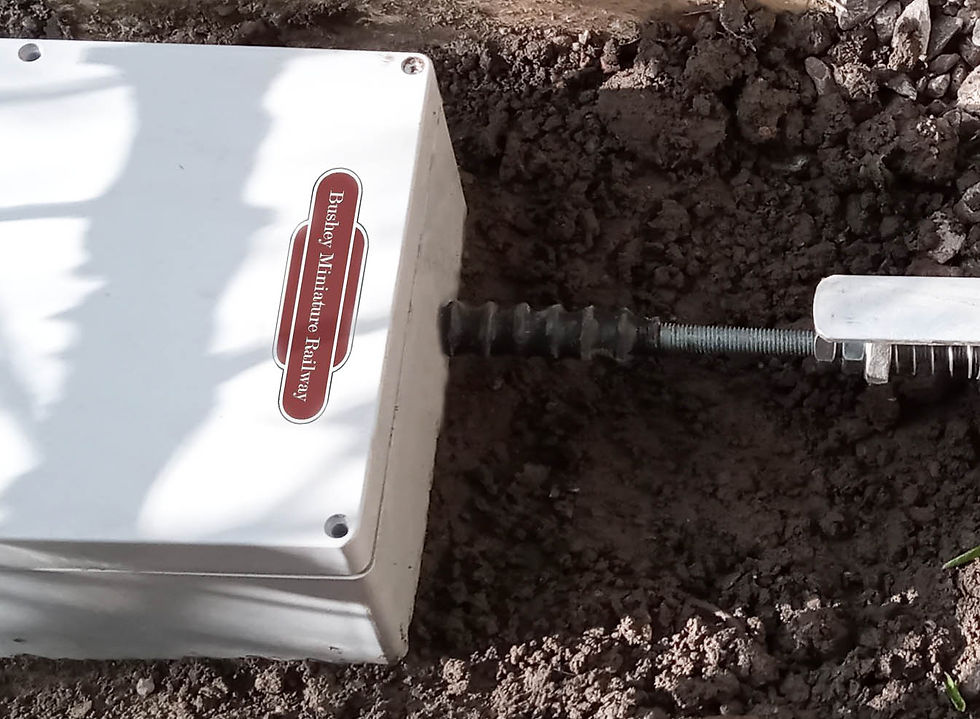
We have built a automated point motor unit for the 30 foot points by the station. This consists of a 12v actuator connected to the point leaver via a sprung mechanism to allow trailing. We are building these for all of our points and initial testing has gone well. We dug a shallow hole and set the unit in concrete on a bed of ballast.
The point motor comes with limit switches inside it that stop the motor when it reaches the end of its travel. We have used the internal limit switches to send a signal to a circuit that controls the signal lights that tell the train driver if its safe to proceed through the points and also which way the points are set. These signals are called Feathers.
A feather signal indicates which route is set on the points ahead to the train driver via a set of 5 white lights. The white lights wont light up until the points are locked safely in position for the set route. While the point blades are in the process of changing, the red stop light is shown.
The circuit we built inside our point motor box does much the same. The signal will have 2 sets of 5 white lights, one for straight ahead and one for left. A red STOP light and a green GO light.
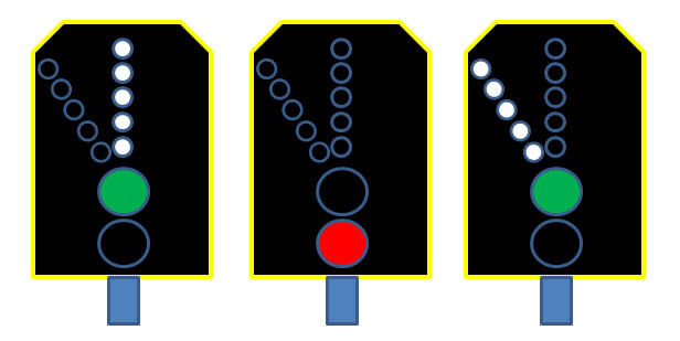
Above: Left image is points set straight ahead and safe to proceed. Centre image is while the point blades are moving to the new position (red stop light). Right image is the points set to left and safe to proceed. All controlled directly from the factory built limit switches inside the point actuator motor, not from any other form of external micro switch mechanism (apart from relay logic circuits using automotive rated relays which are very reliable).

Above: There is a switched cable inside the actuator thats the feed from the in-built limit switches. We connected into this cable (see the blue sleeve where we made the connection) then we fed our cable out of the motor housing via a hole we drilled in the casing.

Above: The smaller cable exiting the casing is the cable we installed . Note we have fitted a heat shrink rubber sleeve around our cable to prevent any abrasion into the cable insulation from the casing. This cable then controls the circuit for the feather signal.
This cable was a bit of a challenge to connect (mainly because of my eyesight) and involved taking the motor apart and removing a few of the gears to access the connections. Its worth doing as the alternative solution was the image below!

Above: A previous attempt at controlling a feather signal using external micro switches triggered by rails fixed to the moving actuator arm. This was unreliable, messy and the signals slightly overlapped in their sequencing which was very difficult to resolve. The new version has none of this and is controlled via the internal limit switches using logic circuits. Signal changes are precise, reliable and maintenance free (and therefore safer).
Below: To keep the hole where the actuator arm comes out of the box as water resistant as possible, we fitted 20mm diameter rubber 'bellows' to seal the gap. These are only cheap and still allow full and free movement. In the image below the arm is at full extension.
So as an example: The system is powered up at the start of the day from the signal box.
Because our unit remembers its last position from the previous running day, the left hand feathers are on and so is the green GO Led. The signalman flicks the switch in the signal box to change the points. The left hand feathers and the green GO led go out, and while the point motor is moving to the new position, the red STOP Led is illuminated. The point motor takes about 5 secs to move, when it reaches the new position, the red STOP Led will go out and the Right hand feathers and the green GO Led will light up, telling the driver its safe to proceed.
This system is very safe as no indication will be given to proceed through the points unless the built in limit switches inside the actuator are triggered, which can’t happen unless the actuator arm has reached its full extension or retraction position. The other advantage is that it doesn’t rely on any external micro switches triggered by the movement of the actuator arm, which can be unreliable (as I found out). This system is driven purely by a relay logic circuit and has no moving parts external to the actuator motor.

Actuator motors can be found on ebay for about £23.00 -very reasonable considering a pre-built unit from Cromer White (all be it including the point mechanism and beautifully built) is over £300!

In the diagram above you can see the actuator included in the home made mechanism to move the point leaver. The damping unit is home made from 7mm threaded rod, 90 degree angle brackets/ washers and Unitsrut ' zeberdies' (a galvanised flat nut with a spring pre attached). All the components are galvenised against the weather.
We have had to replace the springs attached to the Zeberdies to ones that are a bit more substantial though.
'Zeberdies' or sprung channel nuts as they may also be known, can be purchased from Orbital Fasteners in Watford, Herts. As I have mentioned before in my posts, Unistrut is a bit like grownups Meccano, it offers an amazing array of components to make just about anything. I have used it to make the bridge over the old pond and use it at work in the events industry to make all manor of support systems for audio visual equipment.


Comments